Lab 2: Electronics
Continued
Part 1: LEDs In Series & Parallel
LED CIRCUIT IN SERIES
Calculations

I began creating my LED circuit in series with 2 LEDs by calculating how much resistance my circuit needed given a voltage drop of 2A per LED and a maximum current of 20 mA. I solved for resistance using Ohm's law and calculated 50 ohms. Since there were no 50 Ohm resistors in my kit, I made my circuit using the closest resistor I had (100 Ohms). To make my circuit more precise with the correct resistance, I also re-built it with 5 of the 10 Ohm resistors in series so my total resistance would be exactly 50 Ohms. My schematic diagram illustrates the first circuit I created but with a 50 Ohm resistor in place of the 100 Ohm resistor I had to use. A jumper cable is connecting the positive line to the anode of the first LED. The cathode of the first LED is placed in the row below the anode, next to the anode of the second LED. The cathode of the second LED is placed in the row below its anode, and next to another jumper cable connected to ground.
LED CIRCUIT IN PARALLEL

100 Ohm
100 Ohm
Using the 50 Ohms of resistance that I calculated in the previous section (given the voltage drop of 2A per LED and a maximum current of 20 mA), I used the equation for total resistance, and found that I would need two 100 Ohm resistors in parallel to provide 50 Ohms of resistance. In my circuit, two jumper cables starting in the positive line are each placed next to a 100 Ohm resistor. 2 LEDs are placed next to each resistor, with the anode next to the resistor, and the cathode in the row above the anode. Lastly, another jumper cable is placed next to the cathode, and connected to ground.
RGB LED CIRCUIT VIDEO (click & view)

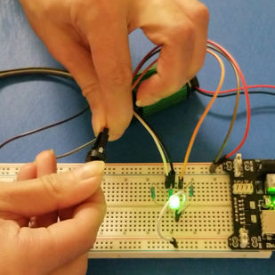
To create this circuit, I replicated the image from the lab assignment, with included a RGB LED, a potentiometer, and a joystick. The joystick bends in both directions, allowing it to act as 2 potentiometers. All 3 potentiometers control the color value of the LED via three leads and three 220 Ohm resistors. To better explain the controls / potentiometers, and the complexity of the RGB LED, my schematic shows the joystick and potentiometer as three different potentiometers, and the RGB LED as three different LEDs each connected to a resistor.
Part 2: Resistors In Series
CALCULATING RESISTANCE, CURRENT & VOLTAGE DROP

Voltage Across Resistor 2 (R2)

Part 3: Resistors In Parallel
Resistance and Current

Voltage Drop

Voltage Across R2

Part 4: Arduino


